Mechanical Engineering · Sheridan College

Khaleel
Siddiqi

Second-year Mechanical Engineering student at Sheridan College. I model parts in SolidWorks, simulate control circuits, and build and troubleshoot real hardware: from winch drives and wind turbines to racing simulator rigs, go-karts and drone field operations.

01

Projects

4 drawings · 5 sheets

Dwg no.01
Title

Small Scale Winch System

Engineering Design & Problem Solving
DateJan–Apr 2026
TypeSolidWorks + Arduino
Sheet1 of 2
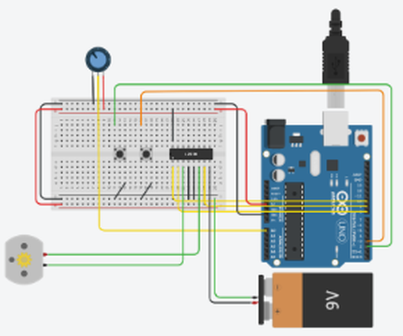
TinkerCAD circuit with Arduino Uno, breadboard, potentiometer, switches, H-bridge, DC motor and 9V battery
Fig 1.1 Arduino motor-control circuit, simulated in TinkerCAD
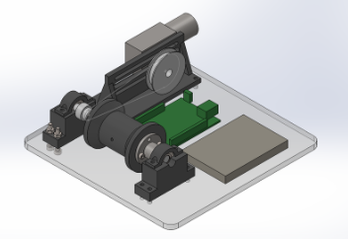
3D CAD render of the winch assembly: motor, belt-driven spool on pillow-block bearings, and controller on a base plate
Fig 1.2 SolidWorks model of the winch assembly
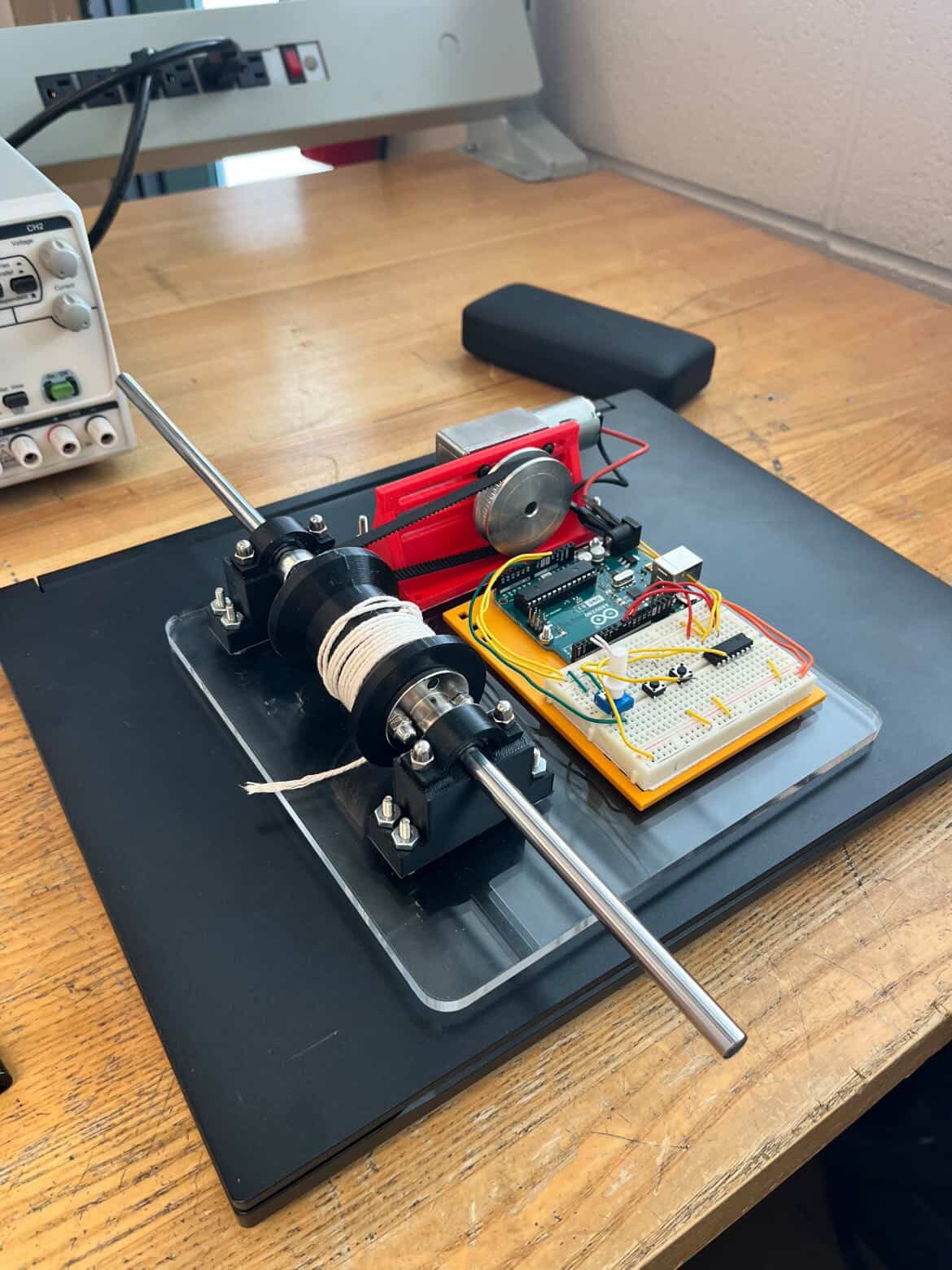
Assembled winch on an acrylic base plate: motor with belt drive, spool on two supports, and Arduino with breadboard
Fig 1.3 Assembled winch prototype
3:1Speed mode: 60T motor gear to 20T spool via belt
1:3Power mode: gears reversed for torque
~10–12 N·mEstimated motor output torque (12 V, ~12 W)
10+ kgLoad the winch was able to pull

What

  • Designing a small-scale winch system to lift and lower loads in a controlled manner
  • Focus on mechanical transmission, motor control, and system modelling
  • Developed as a virtual prototype using CAD and microcontroller simulation tools

How

  • Designed the mechanical parts, structure and spool geometry in SolidWorks
  • Built and tested the Arduino motor control logic as a circuit simulation in TinkerCAD
  • Explored gear ratios, torque requirements, and speed control for safe lifting

Features

  • Dual-mode operation. Speed mode: motor (60T gear) drives the spool (20T gear) via belt for higher speed
  • Power mode: gear configuration reversed for increased torque output
  • 12 V DC motor with worm gear for controlled motion and load holding
  • Potentiometer speed control with a dead zone for safe stopping
  • Direction control through an integrated switch system
  • H-bridge for full motor control (direction and speed)

Results

  • Speed mode gear ratio 60T : 20T = 3:1 (speed increase, torque reduction)
  • Power mode gear ratio 20T : 60T = 1:3 (torque increase)
  • Estimated motor output torque ~10–12 N·m (based on 12 V, ~12 W assumption)
  • Able to pull more than 10 kg
  • Consistent pulling force across variable speeds using potentiometer control
  • Effective torque amplification in power mode via gear switching
Dwg no.01
Title

Winch System: Engineering Drawings

DateJan–Apr 2026
Type5 part drawings
Sheet2 of 2

SolidWorks part drawingsThird-angle projectionScale 1:1All units mmDrawn 26 Mar 2026

DWG 1 Winch Spool · Ø50 flanges, Ø35 drum, Ø8.5 bore
DWG 2 Spool Support · 60 × 20 × 30 block, R11.25 saddle
DWG 3 Spool Bracket · R13 / R11.25 clamp
DWG 4 Motor Mount · Rev 2, 100 × 50 base, slotted upright
DWG 5 Winch Base · 200 × 200 plate, 16 × Ø4 holes
DrawingClick the drawing to zoom

Bill of materials

5 designed parts · 13 purchased items
ItemPartDetailsMake / buyQty
Designed parts · SolidWorks
01Winch SpoolDWG 1 · Ø50 flanges, Ø35 drum3D printed1
02Spool SupportDWG 2 · holds the spool shaft bearings3D printed2
03Spool BracketDWG 3 · clamps over each support3D printed2
04Motor Mount (Rev 2)DWG 4 · redesigned for even load spread after the first print failed3D printed1
05Winch BaseDWG 5 · 200 × 200 mm plateLaser-cut acrylic1
Purchased components
0612 V DC worm gear motor10 RPM worm drive, holds the load when unpoweredBuy1
07Motor driverL293D H-bridgeBuy1
08Arduino UnoPWM speed and direction controlBuy1
09BreadboardControl circuitBuy1
10Potentiometer10 kΩ · proportional speed controlBuy1
11Push buttonsDirection selectBuy2
129 V batteryPowerBuy1
13GT2 pulley, 60 teeth6 mm width, 8 mm bore · motor shaftBuy1
14GT2 pulley, 20 teeth8 mm bore · spool shaftBuy1
152GT-6 closed-loop belt122 mm toothed beltBuy1
16Ball bearingsSteel, 8 × 22 × 7 mmBuy2
17Linear motion rods8 mm × 400 mm, pack of 2Buy1 pack
18FastenersM6 and M8 nuts and boltsBuy1 set
Dwg no.02
Title

Wind Turbine Generator

Exploring Engineering
DateNov–Dec 2025
TypeBuild + test
Sheet1 of 1
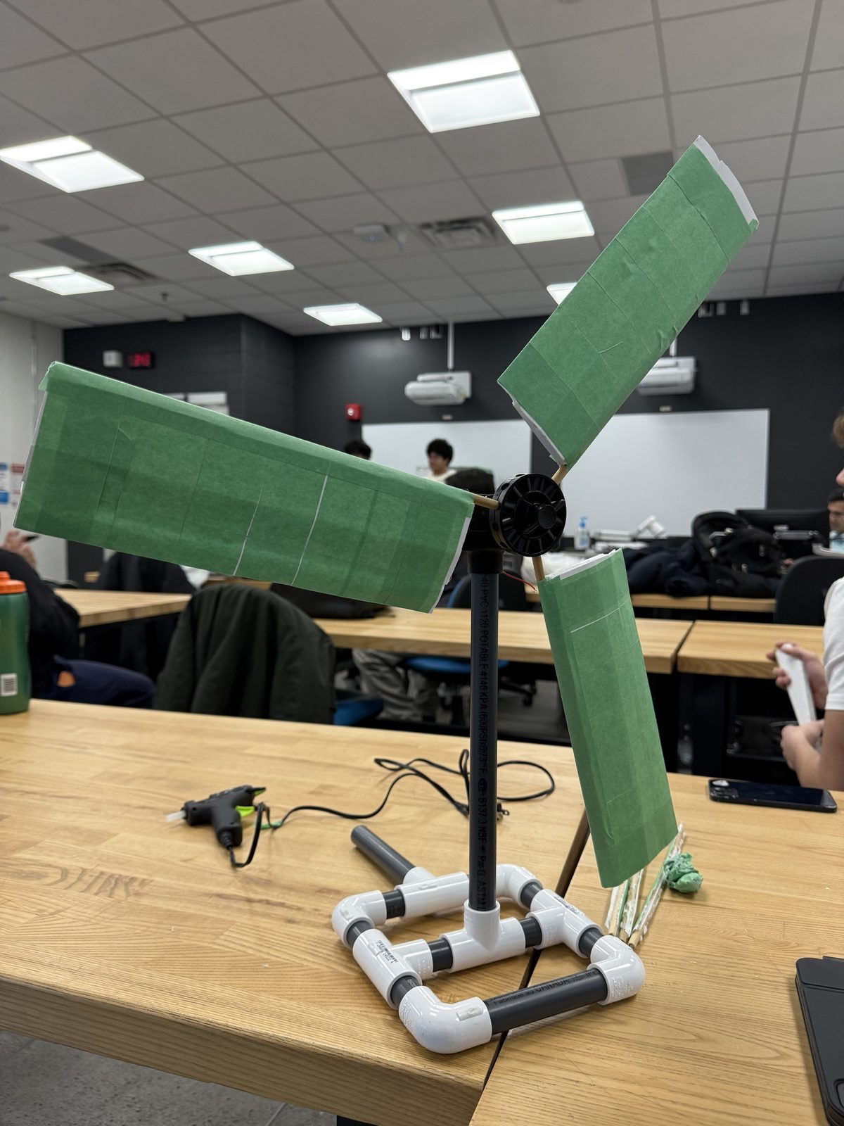
Wind turbine with three green foam-board blades on a PVC pipe base
Fig 2.1 Foam-board rotor on a PVC base
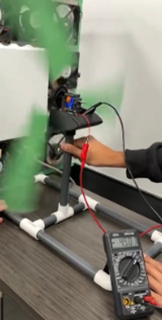
Turbine spinning while voltage output is measured with a multimeter
Fig 2.2 Measuring output under airflow
4.5 VGenerated under test conditions
#1Highest voltage in the class

What

  • Designed and built a wind turbine to convert airflow into electrical energy
  • Focused on blade design, structural stability, and electrical output measurement
  • Objective: maximize voltage generation using low-cost, lightweight materials

How

  • Created airfoil-inspired rotor blades from foam board to reduce weight while keeping surface area
  • Constructed a stable base from PVC piping to support the turbine structure
  • Coupled the rotor to a small generator and tested voltage output under controlled airflow
  • Iteratively adjusted blade angle and spacing to improve rotational efficiency

Results

  • Generated 4.5 volts under test conditions
  • Highest voltage generated in the class
  • Demonstrated effective energy conversion using inexpensive, accessible materials
  • Turbine worked effectively at high wind speeds
Dwg no.03
Title

SolidWorks Claude Agent

DateOct 2026 – now
TypeAutomation
Sheet1 of 1
CSWA / CSWPPractice drawings modelled automatically from their dimensions
VBA + COMSolidWorks macros driven through the COM API
PythonUsed alongside VBA and the COM API

What

  • An AI-assisted workflow that generates SolidWorks VBA macros to model parts automatically
  • Uses dimensions taken from CSWA and CSWP practice drawings as input

Built so far

  • Macros for copper and zinc unit cells for a Materials Science and Engineering lab
  • A parametric wheel macro
  • An interactive GD&T course
  • A replica high-performance HRE car wheel, modelled to analyze the manufacturing processes behind it

Tools

  • SolidWorks, VBA, SolidWorks COM API, Python, Claude
Dwg no.04
Title

Lego Ball Sorter

Exploring Engineering
DateSep–Oct 2025
TypeRobotics
Sheet1 of 1
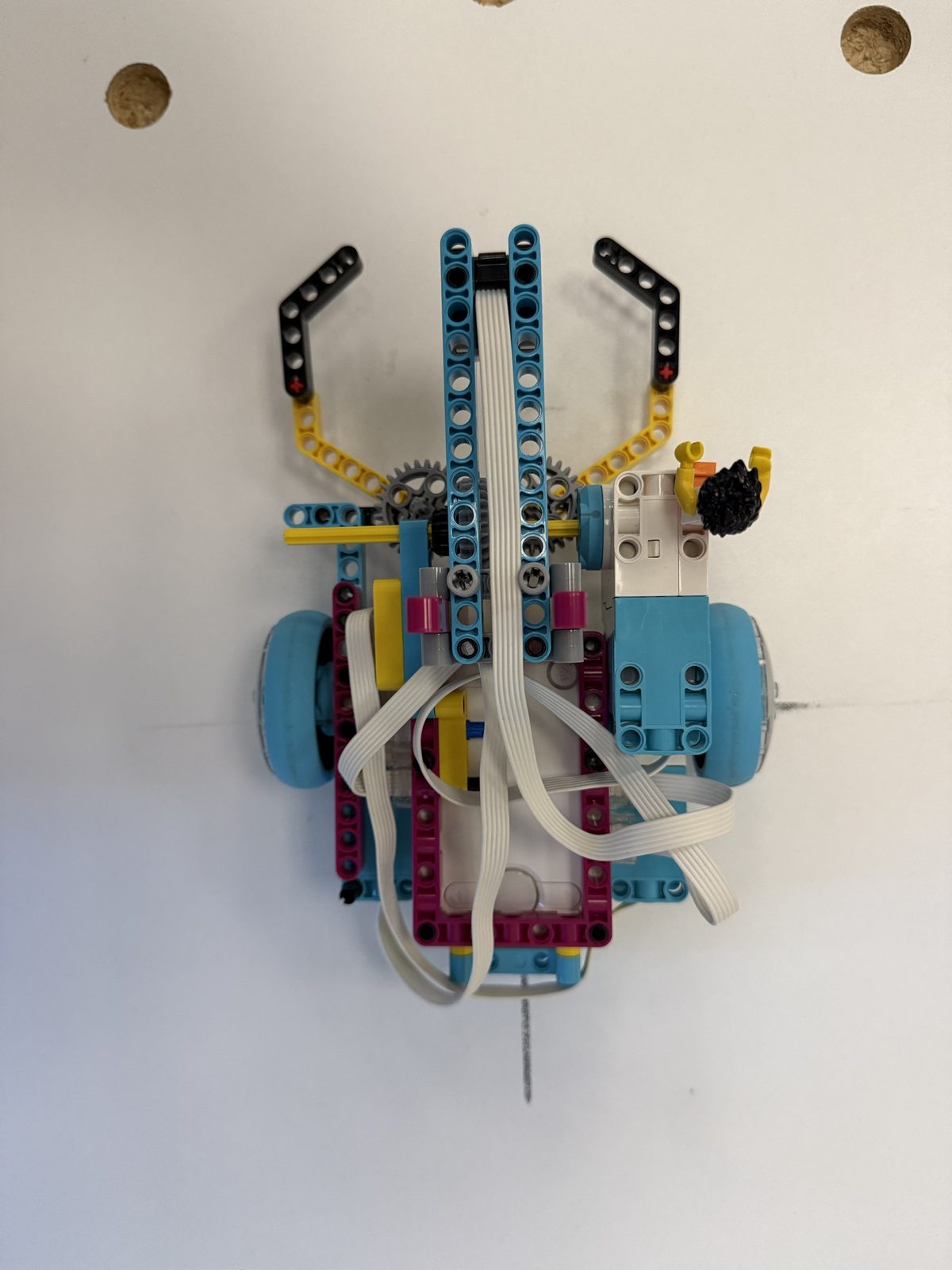
Top view of the LEGO robot with its claw arms
Fig 4.1 Top view
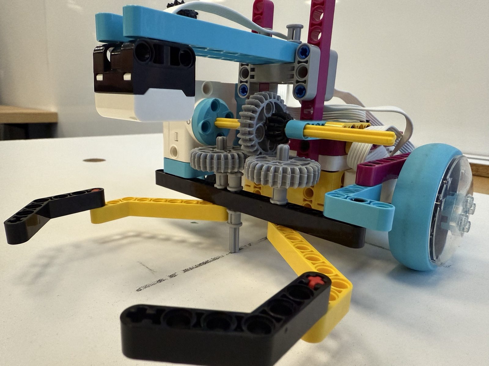
Close-up of the gear-driven claw mechanism and drive wheel
Fig 4.2 Gear-driven claw mechanism
Task layout: start area in the centre, red and blue balls in an arc, goal area on the left Goal area Start move leave
Fig 4.3 Task layout: red balls to the goal, blue balls untouched
30 sFull autonomous task completed
#1Fastest time in the class
20–30 sFaster than other teams on average
0Blue balls disturbed; all red balls sorted

What

  • Designed and built an autonomous robot to identify, collect, and sort coloured balls under time and accuracy constraints
  • Objective: place all red balls into a goal area while leaving blue balls undisturbed
  • Emphasized robotics integration, control systems, and mechanical reliability

How

  • Used a motor-driven wheel system for navigation
  • Added a colour sensor to detect ball colour in real time
  • Designed and implemented a gear-driven claw to grasp and carry one ball at a time
  • Tuned motor speeds and rotation logic to balance speed and positional accuracy

Results

  • Sorted all red balls into the goal area with no disturbance to blue balls
  • Completed the full autonomous task in 30 seconds, the fastest time in the class
  • Outperformed other teams by an average of 20–30 seconds, showing strong control and system optimization
02

Experience

hands-on, troubleshooting-heavy roles

Sep 2026 – PresentMississauga, ON

Shop Supervisor

Sim Hub Race Lounge

  • Moved 8 racing simulator rigs in and out of the shop, then set them up and supported a large-scale event for 10+ families
  • Diagnosed and fixed hardware and software problems on racing simulators to keep downtime low and sessions running smoothly
  • Built and specced out custom sim racing rigs for customers, preparing parts and helping with installation so each full simulator is turnkey for the customer
  • Handled rig builds from component setup through final calibration and testing
May 2026 – Aug 2026Corona, CA

Track Operator / Mechanic

K1 Speed

  • Diagnosed mechanical and performance issues on go-karts by identifying symptoms such as handling, acceleration and operational irregularities
  • Collaborated with mechanics to troubleshoot broken karts, helping determine root causes and final solutions to minimize repair downtime
Jun 2025 – Mar 2026Toronto, ON

Ground Crew

Illumin

  • Solved on-site technical and logistical issues in coordination with the Pilot in Command
  • Supported RPAS (drone) operations during field deployments by setting up, deploying and troubleshooting aircraft
  • Managed equipment logistics, including battery systems, to keep operations safe, reliable and efficient
03

Skills

Mechanical design & CAD

  • SolidWorks
  • 3D modelling
  • Prototyping
  • Mechanical transmissions
  • GD&T
  • Mechanical drawings
  • VBA macros

Hardware & electronics

  • Arduino
  • C++
  • Circuit simulation (TinkerCAD)
  • Hardware troubleshooting
  • Battery systems
  • Simulators

Software & tools

  • Python
  • API integration
  • SolidWorks COM API
  • MS Office
  • English (fluent)
04

Education

Sep 2025 – Apr 2029Expected graduationBrampton, ON

Mechanical Engineering

Sheridan College

  • Maintaining above a 3.0 GPA
  • Developed engineering design and 3D modelling skills in SolidWorks
  • Designed and managed multiple group projects where the final result outperformed the competition
  • Learned engineering drawing principles and applied geometric dimensioning and tolerancing (GD&T) to mechanical designs
05

Certifications

verifiable online

Certificate issued by Dassault Systèmes

SOLIDWORKS · Design

SOLIDWORKS Design Associate (CSWA)

Dassault Systèmes

Issued
November 12, 2026
Credential ID
C-GHWPQ7C8VM
Covers
Part and assembly modelling, sketching, and reading engineering drawings in SOLIDWORKS
06

Contact

Khaleel Siddiqi

Mechanical Engineering student at Sheridan College, based in Brampton, ON. Open to co-op, internship and project opportunities.

LocationBrampton, ON
Phone(647) 646-5079